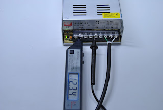
In this post we will be describing how we setup the power supply for our printer. Unfortunately it was not as simple as just plugging a cord into a computer power supply!
Warning
Household electrical current is extremely dangerous and the utmost care must be taken when dealing with it. The following steps are provided only as a guide.
Parts
 |
| Power Supply |
|
 |
| Power Cord |
|
The power supply depicted is a DC 12V 30A Regulated Switching Power Supply Universal 360W.
The power cord is a standard PC power cord.
Step 1 - Prepare AC Power Cord
The first step is to modify a standard computer cable to work with our power supply.

|
Step 1.1
Cut off the end of the power cord that would normally
plug into the power supply of the computer. |
|
 |
Step 1.2
Remove 1-1/2" of the jacket from the end of the power cord.
Be careful to not damage the copper wires. |
|
 |
Step 1.3
Remove all of the excess *white stuff*. |
|
 |
Step 1.4
Strip 1/2" of the insulation from each of the wires. |
|
 |
Step 1.5
Twist the strands of each of the stripped copper wires. |
|
Step 2 - Connect AC Power Cord
Now that the power cord is prepared, we can connect it to the power supply. At this time the power cord should
not be plugged into the wall.
 |
Step 2.1
Remove the screws from the ground, neutral, and live terminals
on the power supply. |
|
 |
Step 2.2
Wrap the exposed copper wires around the screws. The wire
should be wrapped counter clockwise when viewed as above. |
|
 |
Step 2.3
Attach the screws with the wire wrapped around them.
Green to ground, black to neutral (N) and white to live (L). |
|
 |
Step 2.4
Ensure that the copper wires are not exposed and then close
the clear plastic terminal cover. |
|
Step 3 - Tuning Power Supply
It is now time to test and tune the power supply.
Notes
Instead of buying a regulated switching power supply, it is possible to convert an ATX power supply for our purposes. There are many tutorials on the internet on how to do this. However, since the cost was low, we decided to buy a ready power supply instead.


I think this is one of the most significant information for me. And i’m glad reading your article. But should remark on some general things, The web site style is perfect, the articles is really great : D. Good job, cheers j556t
ReplyDelete